The previous description of a speed control drive system was stable and reached the commanded target speed, but it didn't so so in a very "controlled manner". When a step command of 20 or 40 ips was made, the robot accelerated as fast as its motor could go until it got close to the target speed then reduced PWM to stay on speed. This is good for drag racing maybe, but you might want your robot to travel a little more conservatively.
Perhaps you'd want to add some calculations to have the robot accelerate at a consistent rate up to the target speed. And maybe you'd want to make sure it is never commanded beyond a maximum speed. This can be done with limiters.

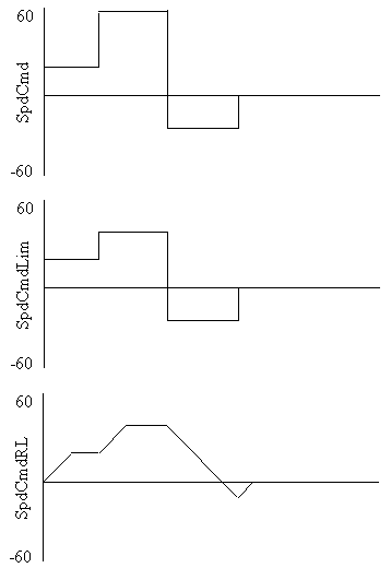
The SpdCmd signal comes from the navigation software and will command + (forward) or - (reverse) commands, but may not always specify reasonable speeds. Hence, the first block, Speed limit, makes sure that the speed to the control equations never gets out of the range +40 ips to -40 ips. To provide a smooth acceleration when the commanded speed changes, the Rate limit block provides a signal, SpdCmdRL, which ramps between previous values and a new command at a maximum rate of +/- 10 inches per second squared.
 The
plots to the right show how these limiters affect an input signal. The top
plot is an (unlimited) signal from the navigation software. It initially
commands 20 ips forward, then 60 ips forward then 25 ips reverse then back to
zero speed.
The speed limiter reduces the 60 ips command to the maximum allowable value of 40 ips. All other commands are within limits and pass through.
The last plot shows the effect of the rate limiter. It allows the command to increase to 20 ips at 10 inches per second squared then holds it at 20 ips. When the (limited) speed command increase to 40 ips, the rate limited output increase smoothly to 40 ips and stays there until the command goes to -25. The rate limited command decreases toward -25, but doesn't get there before the speed command is changed to zero. So the rate limiter returns the command to zero smoothly.
Pseudocode to implement the two limiters can be done as follows:
SpdCmdLim = SpdCmd
IF (SpdCmd > 40) THEN SpdCmdLim = 40
IF (SpdCmd < -40) THEN SpdCmdLim = -40
Accel = SpdCmdLim - SpdCmdRL
IF (Accel > 10/20) THEN Accel = 10/20
IF (Accel < -10/20) THEN Accel = - 10/20
SpdCmdRL = SpdCmdRL + Accel
I'm assuming this code is executed at 20 times per second. The first block of code just limits the input signal to +/- 40 ips. The second block does the rate limiting. It first takes the speed difference between the command and the current rate limited value. This difference (Accel) is then limited to the maximum allowable during a 1/20 second interval. The Accel is then integrated into SpdCmdRL to get the new value.
The outputs are, obviously, the Rate limited speed command signal which can then go to the motor control laws; but also a current acceleration command which may also be useful in the control laws.