Sound activation
To get a 5% reduction in time, a robot may be initiated by a sound rather than a manual action. The rules for the Trinity contest define this as a 3 to 4 KHz
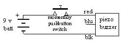
tone of which the Radio Shack #273-075 piezo buzzer is an example.The circuits below cover the sound generator itself; and a method to detect the sound and output a signal to the robot's processor.
The tone generator is simple, just hook a 9 volt battery to the buzzer through a momentary switch. I think the left over blue wire on the buzzer was to provide a pulsing output.
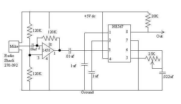
The tone detector is a bit more complicated. The circuit below works for me and is relatively simple. Other circuits can be found on the internet.
This circuit uses a Radio Shack microphone amplified by half of a 1458 dual op amp. The two 120K resistors attached to pin 3 ensure that the output of the opamp will be about at the midpoint between the 5 volt supply and ground. These resistors' value is non critical, but should be the same. The 0.01 uf capacitor between the mike and pin 2 keep any DC level from the microphone from getting to the opamp.
The 120K resistor from pin 1 to 2 establishes the gain of the amplifier. This resistor can be changed to make the detector as sensitive as you want. Increase the resistance to get more range. Sensitivity is a bit of a problem. Sometimes my detector will pick up the tone from many (10 to 20 feet away), but other times it might miss it from a few feet away. So, for competition, I will be sure to hold it about a foot away.
The NE567 is a tone decoder. It is wired basically to an example in the application notes. (refs to buy, spec & note). Basically, it has an oscillator which is set to a desired frequency by varying the 25K resistor (or the .022 uf capacitor). The output of the amplifier is compared by the 567 to the oscillator frequency. If they are the same, the output is driven low (???). The matching of the frequencies needs a close match; so, I used a 10 turn trimpot for the 25K resistor so I could make fine adjustments.
The 20K pull up resistor on the output can be changed, or deleted, to meet your processor's requirements.
Picture of finished module?