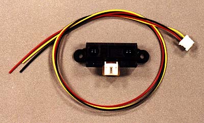
Sharp GP2D12 IR range sensor.

This infrared range sensor provides a pretty good indication of distance over a range from as little as 4 inches to as much as 30 inches. The sensor provides an analog output voltage inversely proportional to the distance.
It is available from www.acroname.com for $13.50. Sharp doesn't seem to have a detailed spec for this partnumber on their website, but they do have data on a similar sensor (which you might even prefer). It is the GP2D02, which has a serial digital output rather than analog. It's specs can be found at: http://www.sharpmeg.com/products/opto/pdf/gp2d02.pdf
The sensor works by projecting a small beam of IR light (looks approximately 1/4 inch diameter at a range of around 10 inches). It then measures the angle at which the beam returns on a IR receiver which is offset about 3/4 inch from the transmitter. So, this sensor differs from other range sensors, like sonar, in that it only detects objects in the specific direction that it is pointed.
The output signal is sometimes referred to as "non-linear", but, in fact, it is very accurately inversely proportional to the distance. Hence, after reading it in as an analog value, you can easily convert it to linear distance by dividing it into a constant: i.e. distance = constant/(analog reading). This method works very well down to a distance of about 4 inches. Below this value, the sensor is unusable as it outputs voltages which also occur at longer distances making the results ambiguous.
The best solution for the ambiguity is to mount the sensor about 4 inches inboard from the edge of the robot so that it cannot get within 4 inches of an object. And to calibrate the sensor to make it relative to whatever point you want to use ( the center of your robot, the edge, or whatever), you can add a calibration number to the distance equation for each sensor to make the distance accurate.
There is a Sharp application note available at: http://www.sharpmeg.com/products/opto/appnotes/gp2d02_5.pdf. This note is specific to the D02 and D05 models of the sensor; but are believed to be applicable to the D12 as well. In particular, this note recommends grounding the conductive plastic enclosure of the sensor; and, if looking at a moving surface (like passing by a wall in the Trinity maze), the sensor should be oriented perpendicular to the direction of motion. I have done some testing and found that the vertical orientation of a side facing D12 did improve the fidelity of the signal received, particularly when scanning past corners. I found little noticeable improvement by grounding the sensor case. However, others have reported significant differences, and following these guidelines is probably a good idea in a new design. It can't hurt (that I know of).
One interesting characteristic I observed was that while scanning a wall (at 90 degrees to the robots direction of motion down the hall, I got some spurious values when the end of the wall was reach. Rather than the sensor value going directly from the nominal 9 inches (center of hall) to a large value (no wall in sight), the sensor sometimes gave out 2 or 3 values of intermediate range...maybe 12 to 15 inches. Since I was believing any values of less than 15 inches to be indications of a wall, my steering control sometimes made transient turns for a few computation cycles before the wall became clearly out of range. This problem can perhaps be best compensated in software by filtering the input data in some way. (P.S. I was reading the sensor data at 61 hz (every 16 milliseconds).
The sensors also occasionally gave off spurious single point values which often represented large distances. I had logic which change the robot's direction when the end of a wall was detected. And I didn't want it to trip due to spurious values. So I usually required 3 continuous values of a long distance before I would believe that the end of the wall had been reached.
I used one D12 sensor to measure the distance forward to detect upcoming walls. Approaching walls at up to 20 inches/second, this sensor gave very inaccurate data at distances much over a foot. It indicated the distance as being much closer than it really was until the sensor got pretty close to the wall. I have no idea why this occurred, but it's something to watch out for.
Another characteristic, perhaps of my own implementation, is that when the wall was far away, the analog reading would sometimes go all the way down to zero. My 68HC912B32 processor has the interesting method of handling divide-by-zero (in the above distance equation) by returning a zero. Hence, very long distances were occasionally interpreted as zero distance. I had to add special logic to the distance calculation to make it output a large value specifically if the analog signal in the denominator was zero.
The GP2D12 has been reported to be susceptible to "noise". In particular, it has been reported that running several GP2D12s simultaneously might result in erroneous data. I have been running 4 GP2D12s from the same 7805 regulator (down from 12 vdc) and have occasionally had some bad data. I had cured this by attaching a 10 uf tantalum cap directly to the power input to the GP2D12 as has been suggested elsewhere.
 To
understand this problem better, I tested the effects of the sensor on the power
source. I did this using my proposed future hookup scheme for the sensors
where each has its own dedicated voltage regulator to avoid (hopefully) any
noise coupling between them.
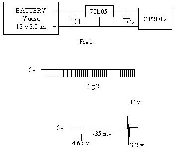
The circuit was a show in Fig 1. There was approximately 3 feet of hookup wire between the battery and the voltage regulator and about 8 inches of wire between the regulator and the GP2D12 (the connector wiring supplied by Acroname).
With C1 and C2 left out, the voltage waveform on the power at the output of the regulator was as shown in Fig 2. There is a train of 32 negative going pulses spaced at 1 msec followed by a gap of 8 milliseconds. For a total period of 40 msec. This pattern repeats continuously. Looking at the output of the sensor LED with a phototransistor, it is apparent that each pulse is a flash of the LED. Each pulse has an amplitude of - 35 mv from the 5 v power.
Looking closely at each pulse, the "noise" content is more apparent. Each pulse has a width of about 130 usec. Transients occur at the leading and trailing edge of each pulse. Each transient has a width of about 500 nsec. The ones at the trailing edge are largest with a single excursion to 11 vdc and back down to 3.2 vdc before returning to the normal 5 vdc.
It is not apparent that these transients cause the sensor any problem, but the datasheet for the 78L05 recommends a minimum capacitance on the output of 0.01 uf "to limit high frequency noise bandwidth", so I added one and it reduced the trailing edge spikes to 6.4 and 4.5 volts. Adding much larger capacitance (.47 uf) caused high frequency ringing (25 Mhz) at the transients. Since it isnít clear that the noise is a problem, I decided to use the 0.01 uf at C2.
Interestingly, the 35 mv negative pulses can be seen all the way back to the battery terminals. By that point, the spikes are about +/- 100 mv.
Adding a 1 uf tantalum cap at the input to the 78L05 reduced the transients at the battery to 10 mv (with no impact on the 35 mv pulse). The use of C1 had negligible impact on the waveform at the output of the 78L05.
A final warning, while testing the installation of a GP2D15 IR sensor on my firefighter, I discovered that it is very sensitive to a candle flame. The D15 is very similar in appearance to the D12, but it provides only a logic output signal indicating whether an object is within a preset distance from the sensor. Pointing this sensor approximately toward a candle flame, at a distance of at least 3 feet away, will cause the sensor to output the "object within proximity" logic state even though no such object exists. I suspect therefore, that a D12 may give erroneous range data if a candle is in sight.