The Famous Servo Hack
This page documents the
steps required to modify a radio control servo to provide continuous rotation
such that the servo can be used as a drive motor for a small robot. Most
pictures can be clicked to get a larger version.
This modification procedure is
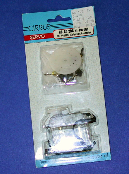
directed towards the Cirrus CS-60 2BB servo. This servo is available from
Hobby People (www.hobbypeople.net) where you can order it on-line; or find a
store near you. This servo is relatively inexpensive and is suitable for
the continuous rotation modification as well as modification to add a sensor to provide an
encoder function. Click here for more technical data
on the CS-60 2BB.
 There are many other servos which may be modified for continuous rotation in a
similar (but usually not identical) process. You can find other sets
of instructions by searching the web. This servo has a little more torque
than the "standard" servo, is rated at 6.0 vdc (which gives more speed and
torque) and has a transparent case which is convenient for inspecting the
gears.
There are many other servos which may be modified for continuous rotation in a
similar (but usually not identical) process. You can find other sets
of instructions by searching the web. This servo has a little more torque
than the "standard" servo, is rated at 6.0 vdc (which gives more speed and
torque) and has a transparent case which is convenient for inspecting the
gears.
If you want to use a different part
number servo, be aware that some servos (including the Cirrus CS-50 and
CS-400BB) do not have a full 360 degrees of teeth on the output
gear. This is apparently a cost savings measure since the servo is
only designed to rotate slightly over 180 degrees. Hence, the clear case
of the CS-60 and CS-80 series is convenient for verifying the presence of a 360
degree gear before buying the servo.
The Cirrus servos are available with 3 sets of features. The "standard" servo has all plastic gears
and plastic or metal bushings for bearings. The "BB" models have
at least one ball bearing on the output shaft while the "2BB" servos
have two ball bearings. The "MG" option replaces some or all of
the plastic gears with metal gears. The metal gear option provides a lot
more durability to the servo.
PARTS AND TOOLS REQUIRED:
2 Servos, Cirrus CS-60 2BB Hi-Torque
Super glue (optional)
Small Phillips head screw driver
 Razor blade or equivalent to cut tab off.
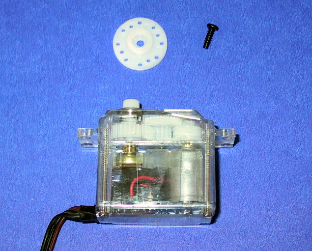
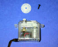
1. Remove the output wheel on the output shaft
(if installed). Use a small Phillips head screwdriver to remove the screw
in the center of the output wheel; then just pull the wheel off.
.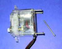
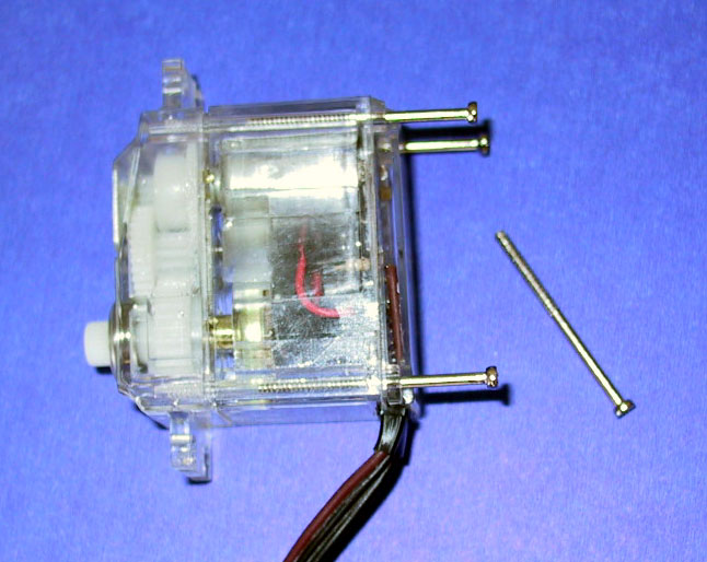
2. Remove the four housing screws from the bottom corners
of the servo Try to keep the bottom plastic cover in place, but it
will probably come loose anyway. No problem, it easily fits back in place.
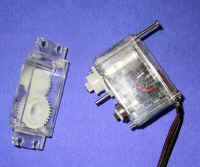
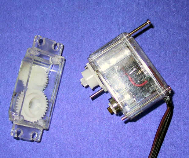
3. Split the case at the line just below the gears and the
mounting flanges. The output gear and an intermediate gear will come off with
the top of the case. Keep an eye on the intermediate gear in the top as it
isn't well attached and could get lost.
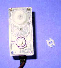 4.
In the lower case, beneath where the output gear rested, you will see a ball
bearing with a brass, flatted shaft in the center with a white plastic clip
around the brass shaft. This white clip is the coupling between the output
gear and the position potentiometer on the other end of the brass shaft.
The pot can be seen by looking through the side of the transparent case.
Remove the white coupling clip. It is just pressed on over the brass shaft
and can be pried off easily. This disconnects the potentiometer so
that it will not turn as the servo output gear turns.
4.
In the lower case, beneath where the output gear rested, you will see a ball
bearing with a brass, flatted shaft in the center with a white plastic clip
around the brass shaft. This white clip is the coupling between the output
gear and the position potentiometer on the other end of the brass shaft.
The pot can be seen by looking through the side of the transparent case.
Remove the white coupling clip. It is just pressed on over the brass shaft
and can be pried off easily. This disconnects the potentiometer so
that it will not turn as the servo output gear turns.
5. Some servo hacks require the pot to be removed and
replaced by resistors. In this case, removal is not necessary.
However, the pot must be moved to its center position. The brass shaft may
be turned with your fingers to determine the maximum right and left positions;
and then return it to the center as close as you can estimate. This will
probably result in some error, but any offset can be accounted for in
software. An alternate scheme to determine the center point is to attach
the servo to a controller which is sending out a 1.5 millisecond pulse (center
position). You can then find the center position of the pot by rotating
the brass shaft until the motor stops moving.
You may want to lock the brass shaft into
position after placing it in the proper center point. This step is
optional, as with the white plastic clip removed, the output gear does not touch
the brass shaft and it tends to remain where you put it. If you want to
lock it in place, apply a small drop of super glue to the side of the brass
shaft so it can run down the side. DO NOT get any super glue into the ball
bearing around the shaft. After a few minutes, test the glue by attempting
to gently rotate the brass shaft. Do not apply too much force or the glue
bond may break. Leaving the shaft unlocked has the advantage that
you can restore the servo to the normal configuration.
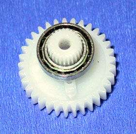
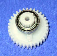 6.
Press the output gear out of the top housing. This can be done by holding
the housing upside down so that the shaft is against a table, then just press
down on the housing and the shaft will press out. Remove the output
gear. Also, set the intermediate gear aside as it will now be loose. Below
the ball bearing, you will see a small plastic tab on the gear (at bottom of
adjoining picture). This tab is to ensure that the servo does not travel
more than 180 degrees and must be removed to allow continuous rotation.
(the stops on the upper housing, which this tab runs into, do not have to be
removed).
6.
Press the output gear out of the top housing. This can be done by holding
the housing upside down so that the shaft is against a table, then just press
down on the housing and the shaft will press out. Remove the output
gear. Also, set the intermediate gear aside as it will now be loose. Below
the ball bearing, you will see a small plastic tab on the gear (at bottom of
adjoining picture). This tab is to ensure that the servo does not travel
more than 180 degrees and must be removed to allow continuous rotation.
(the stops on the upper housing, which this tab runs into, do not have to be
removed).
Use your favorite tool to remove
the plastic tab: Wire cutters, Exacto knife, Dremel tool, etc. Try
to get it all off as even a small piece may hit the tabs on the housing and
cause the servo to jam.
7. Now the servo can be reassembled.
Press the output gear back into the upper housing using your fingers. Make
sure the intermediate gear is in place above it.
8. The top servo housing can now be reattached
to the lower housing. make sure that the shaft for the intermediate gear
properly goes into the gear; and gently align the upper and lower housings so
that the gears will mesh together. Turn the output shaft a bit, if
necessary, to get the gear teeth to line up. When the two housings are
together, you can place an output wheel on the servo output shaft and rotate it
gently (may take some force, but go slowly) to ensure that the gears are all
engaged and moving freely. Don't push too hard if it feels jammed, or you
might strip the gears. A safer test is to hook it up to a controller and
try to drive it. If it is jammed, it won't turn...and won't strip.
9. Reinstall the four screws into the bottom
of the servo and the modification is complete. Congratulations.
 There are many other servos which may be modified for continuous rotation in a
similar (but usually not identical) process. You can find other sets
of instructions by searching the web. This servo has a little more torque
than the "standard" servo, is rated at 6.0 vdc (which gives more speed and
torque) and has a transparent case which is convenient for inspecting the
gears.
There are many other servos which may be modified for continuous rotation in a
similar (but usually not identical) process. You can find other sets
of instructions by searching the web. This servo has a little more torque
than the "standard" servo, is rated at 6.0 vdc (which gives more speed and
torque) and has a transparent case which is convenient for inspecting the
gears.