POWER SUPPLY
Ebot needs electrical power for it's motors, sensors and processor. This section will provide directions on how to build one or more types.
There are several ways to approach providing electrical power for your Ebot.
The simplest is to add batteries to meet each voltage/current requirement. For the very basic Ebot, this will probably be batteries for 5 or 6 volts to drive the hacked servo motors, and, perhaps, a 9 volt battery to drive the processor (depending on what processor you have chosen).
The basic requirements for a power source are: the right voltage, adequate current capability, and "clean" enough voltage. Clean means that the voltage supplied is steady enough to meet the requirements of the using systems. In particular, a processor may exhibit erratic performance if its power source has voltage transients.
Many items on a robot may cause power transients. Especially motors which will be pulse width modulated. The pulse width modulation results in electrical current flowing in a square wave type pattern; and switching current on and off like that can cause the voltage to fluctuate; usually noted as spikes as well as a reduction in the voltage when the current is switched on and an increase (back toward normal) when it is off.
Many items on a robot don't care too much about power transient; like motors. However, the processor should be provided with very clean power to ensure reliable operation. This can most easily be accomplished by having separate power sources for the servo motors and the processor. Many sensors also need clean power.
The servos you hacked for the drive motors are commonly rated for 4.8 vdc (which is 4 NiCad cells) up to 6.0 vdc as the cirrus servo spec recommended these servos will handle. If you want to get maximum speed and performance out of your Ebot, you will want to run the higher voltage. (motor top speed and torque is proportional to the voltage applied).
So, for a 6.0 volt battery, you will need 4 standard flashlight type batteries (which are about 1.5 volts each) or 5 NiCad batteries (which are 1.2 volts each). You can run whatever SIZE batteries you want to fit onto your robot. AA cells, C Cells or D cells, or even a 6 volt lantern battery. Larger batteries will give a higher current capability, and longer time before the batteries go dead; but, they will be heavier and may be hard to find room for on a small robot like Ebot. The following drawing shows 4 C cells mounted between the motors and the caster.
Many processor chips or boards have built in voltage regulators and can accept a power supply as long as it provides a voltage in some range (e.g. 4.5 to 15 volts). A standard 9 volt battery is often used for this kind of setup. It is small and, being independent of the motor batteries, will provide clean power. Of course, being small, it may not last too long before it needs replacing.
I, personally, HATE the idea of constantly buying batteries to run my robots. I usually build a power supply which can supply all the necessary voltages from a single rechargeable battery. But, for Ebot, we'll start with an easy system and, perhaps, build a better one later. Of course, you can buy NiCad rechargeable batteries in the C cell size and 9 volt size.
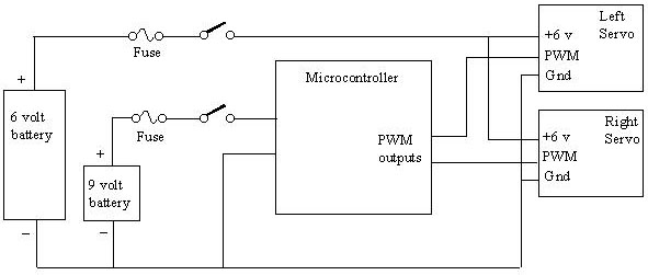
So, above is the basic wiring for the simplest version of Ebot. Besides the power, it shows the two PWM control signals for the two servos which are the only other required wires to get running.
If using the above design, make sure your microcontroller (or controller board) is designed to run from 9 volts. If it has a specific voltage requirement (e.g. 5.0 vdc), you will have to add a voltage regulator between the switch and the microcontroller. (Voltage regulator to be added here someday, perhaps)
The 9 volt battery powers the microcontroller with a switch to turn it on and off, and a fuse to protect the wiring against shorts. The fuse should be larger than the power requirement spec for your microcontroller. In most cases, a 0.25 amp fuse should be adequate.
The 6 volt battery pack powers the two servos with a similar switch and fuse. In this case, the servos may draw more current so a larger fuse may be required. Perhaps, a 1.0 amp.
Note: if using relatively small carbon zinc or alkaline batteries, the fuses could maybe be optional as the batteries probably can't supply enough current to burn wires up. However, if you use larger SLA batteries or NiCads, they can supply a LOT of current through a short and the fuse becomes much more essential to a safe design.
The drawing above shows two separate switches. You can combine these into a Double Pole/Single Terminal switch (DPST) if you wish, but you might want to leave them separate so you can power the microcontroller alone to do programming and testing without running down your servo battery.
Also, notice that the grounds of both batteries are tied together. This is necessary so that the PWM signals will have the same ground reference voltage level for both the microcontroller and the servos.