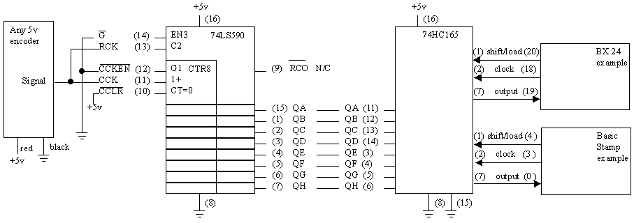
The following scheme was presented by Steve Vorres (7/14/01) which uses some external hardware and the serial interface of the Basic Stamp to read one or more encoders without the need to poll for pulse transitions. The pulse count data can be read whenever the software desires it.

A 74LS590 is used as a counter of the incoming pulses. The counter has 8 bits of resolution and will count up to 255 then automatically start again at 0. It requires a TTL compatible signal from the encoder which will most likely be available from a commercial encoder, but may require you to tailor your circuitry for a homebrew encoder.
The 8 bit count is always available on the 8 pins Qa to Qh from the 74LS590, and is wired to the input pins of a 74HC165 which is a parallel in/serial out chip.
The Basic Stamp (or equivalent, e.g. BX24) interfaces with the 74HC165 with three pins using its SHIFTIN instruction.
Two sample programs follow, one written for the basic stamp and one for the BX24. The wiring to either processor is shown in the drawing above. In each program, a pulse is sent to the Load pin of the 74x165 to latch the data that is currently on the eight input pins. The latched data is then sent out on the output pin to the processor each time a clock pulse is applied by the SHIFTIN instruction.
First, for the Basic Stamp, from: StampWorks Manual Version 1.1
' ========================================================================
' File: 74x165.BS2
'
'Read eight switches using only three lines and a 74x165 shift register
' =======================================================================
D_in CON
0 ' shift data
(74x165.7)
Clock CON
3 ' shift
clock (74x165.2)
Load CON
4 ' input load
(74x165.1)
Switches VAR Byte ' inputs switches
'
-----------------------------------------------------------------------------------------------------------
Initialize:
HIGH
load
' make output; initialize to 1
'
-----------------------------------------------------------------------------------------------------------
Main:
GOSUB ReadSwitches
' read input from 74x165
DEBUG Home, IBINS switches '
display binary mode
PAUSE 100
GOTO
Main
' do it again
END
'
----------------------------------------------------------------------------------------------------------
ReadSwitches:
PULSOUT
Load,3
' grab the inputs
SHIFTIN D_in,Clock,MSBPre,
[switches] ' shift them in
RETURN
'----------------------------------------------------------------------------------------------------------
Next, for the BX24,
' Rotary Encoder July 12 2001
------------------------------------------------------------------------
' This program takes in 3 inputs from a 74LS165 Parallel in/Serial out
shift register.
' A 74LS590 counter counts the inputs from an optical encoder and feeds the data
to the 74LS165 shift
' register.
' The Basic X -24 then uses a shiftin command to convert the data to a single
byte
' The routine takes about 250 uS to execute, not including the time to write to
the screen.
'
' by Steve Vorres 858-496-0971 svorres@lsil.com
sub main()
dim encoder as byte
' set up pins 20, 19 and 18 to 5 volts
call putpin (20,1)
call putpin (18,1)
call putpin (19,1)
start:
' load the contents of the counter into the shift register
call pulseout (20,1,0)
' shift the bits out to the BasicX
encoder = shiftin (19,18,8)
' print the results
debug.print "Encoder = ";cstr (encoder)
goto start
End Sub
'----------------------------------------------------------------------------------------------------------
To determine how far the encoder has moved, it is necessary to subtract the current number read in from the previous number. Since this counter only counts up, the resulting difference should always be in the range from 0 to 255. You must limit your encoder resolution, motor speed and/or interval between reading the counter so that the encoder cannot turn more than 255 pulses between readings or you will get erroneous data.
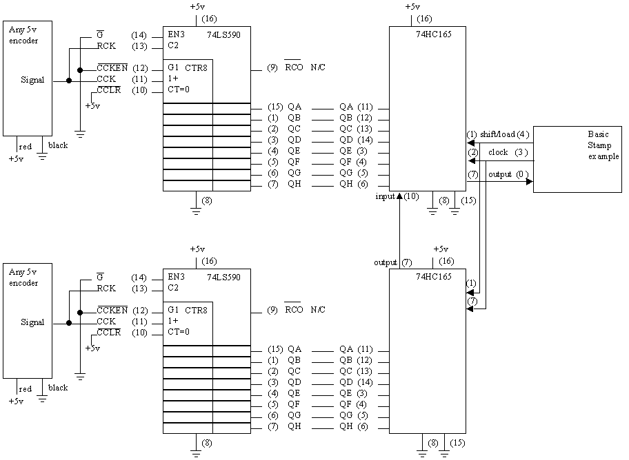
Having read one encoder from the above circuit, the circuitry can be modified to read two encoders into the processor through the same 3 pins.

This circuit is the same as two of the previous circuits, except that the 74HC165s are wired together such the the data from the lower 74HC165 is shifted into the upper 74HC165 and the output of the upper chip goes to the processor. The Load and Clock signals are wired to both 74HC165s to make them both shift together, and the software must be modified to input 16 bits rather than 8.
For the Basic Stamp, you can define 2
variables: switchesA VAR Byte
switchesB VAR Byte
and change the shiftin instruction to: SHIFTIN D_in,Clock,MSBPre,[switchesA,switchesB]
For the BX -24, ???