Motorola 68HC912B32
The 68HC12 series of microcontrollers is an
upgrade to the 68HC11 commonly used in robotics as the controller on the popular
Handiboards and Botboards and many other homebuilt boards. The HC11 series
was a good processor for robotics. The HC12 series provides more speed,
memory and I/O capability while being upwardly compatible with the HC11
instruction set.
The HC12 has the disadvantage of only being
available as a surface mount chip, hence making it difficult to make your own
boards unless you are quite experienced. However, the chip is available
from several manufacturers already built onto a board. The particular
implementation that I will present is the Adapt912 built by Technological Arts
in Toronto (www.technologicalarts.com).
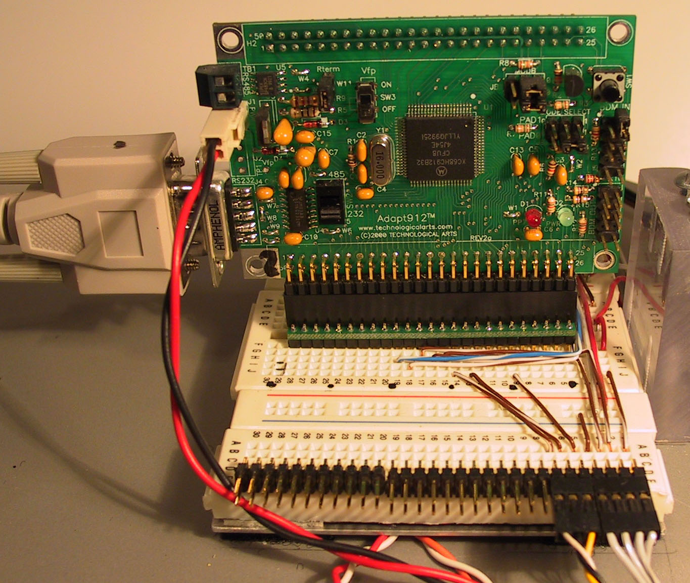
 The Adapt912 provides all the additional hardware necessary to get the HC912B32
running: Voltage regulator, RS232 interface, power on reset control, and
all I/O pins are brought out to a connector. TechArts provides an
adaptor in their starter kit which permits the Adapt912 to be plugged right into a standard
protoboard. This makes it very easy to interface to many types of sensors
and actuators with no additional circuitry and just using jumper wires on the
protoboard; or even to construct interface circuitry right on the
protoboard.
The Adapt912 provides all the additional hardware necessary to get the HC912B32
running: Voltage regulator, RS232 interface, power on reset control, and
all I/O pins are brought out to a connector. TechArts provides an
adaptor in their starter kit which permits the Adapt912 to be plugged right into a standard
protoboard. This makes it very easy to interface to many types of sensors
and actuators with no additional circuitry and just using jumper wires on the
protoboard; or even to construct interface circuitry right on the
protoboard.
Click on picture to enlarge.
The basic HC912B32 chip has 32K or Flash
memory. The top 2K is used for a bootload program permitting the rest of
the Flash (or other RAM or EEPROM) to be programmed over a serial bus from your
PC. So, 30K is available for user code. My firefighting robot has
over 50 pages of C code in it and is using only 22K of the 30. The chip
also has 1K of RAM and 768 bytes of EEPROM.
TechArts also has a 64K RAM expansion board
available which can be convenient during development or for expanded data
storage. But, you don't NEED it to do serious programming.
There has been some concern that the Flash
memory could only be erased and programmed for a limited number of cycles (a few
hundred). There has been quite a bit of discussion of this on the
internet; and the consensus seems to be that the "few hundred" cycles
is a real worst case scenario. Many people (myself included) have gone far
beyond a few hundred and have experienced no failures.
The 912 has a large number of I/O pins
(63). The 8 analog input pins can be initialized for continuous Analog to
Digital (ATD)
conversion. Hence, you do not have to do any inline code to accomplish
each ATD input. Just read the latest value from a memory location.
The 4 PWM outputs are completed programmable and can be set up so that you just
have to store a number to memory to update the PWM duty cycle. It has a
good number of timers and input capture/output compare pins. Almost all
pins not being used for a special I/O feature (e.g. PWM) can be set up as general
discrete I/O pins. The 912 has many interrupts, both external (2) and
internal (timers, ATD, captures, etc) as well as a real time clock interrupt.
Almost all the input pins have internal
programmable "pull-ups" saving a little external circuitry.
The "Starter Kit" version of the
Adapt912 provides the Adapt912 card, a connector to attach power to the card,
the adaptor plug to interface the card to a protoboard, hardcopy documentation
for the 912B32 chip, and a CDrom with much additional info including Motorola's
freeware assembler, Karl Lunt's Sbasic compiler and many
coding examples.. A freeware C compiler is also available. The TechArts website provides links to many additional
sources of information and coding examples including Motorola's large collection
of on-line documentation.
With the software supplied with the starter
kit, you can immediately hook the board up to a 9 volt battery, attach a
standard serial cable from the board to your PC and bring up the built in
monitor/debug software which comes preinstalled in the Flash memory. You
can use the Windows accessory "hyperterminal" to communicate.
You can then copy the Sbasic and Assembler from the CDrom to your computer and
start programming. Install the board onto a protoboard and you can start
attaching sensors and servos.
With all this said, the Adapt912 may
not be the place for a neophyte programmer to start. You must understand
or learn a fair amount about how a microcontroller works to get going. All
the information and examples is available, but it's a much bigger jump to get
going than a Basic Stamp.
But, if you already are an experienced
programmer, or are bumping into the performance limitations of the Stamp, the
Adapt912 provides a big leap in performance capability for a reasonable cost.
If you are interested, I recommend you go to their
website and investigate all the information available (mostly in the
"resources" section).
 The Adapt912 provides all the additional hardware necessary to get the HC912B32
running: Voltage regulator, RS232 interface, power on reset control, and
all I/O pins are brought out to a connector. TechArts provides an
adaptor in their starter kit which permits the Adapt912 to be plugged right into a standard
protoboard. This makes it very easy to interface to many types of sensors
and actuators with no additional circuitry and just using jumper wires on the
protoboard; or even to construct interface circuitry right on the
protoboard.
The Adapt912 provides all the additional hardware necessary to get the HC912B32
running: Voltage regulator, RS232 interface, power on reset control, and
all I/O pins are brought out to a connector. TechArts provides an
adaptor in their starter kit which permits the Adapt912 to be plugged right into a standard
protoboard. This makes it very easy to interface to many types of sensors
and actuators with no additional circuitry and just using jumper wires on the
protoboard; or even to construct interface circuitry right on the
protoboard.