PID equations are not always used the same way. Selection of the proper terms of the equations depends on the configuration of your robot.
In order to explain things more clearly in later pages, I'm going to define the robots that I'll be using as examples.
The examples I use will be based on on steering and motor control functions. Basically, there will be two kinds of steering and two kinds of motor (speed) control.
Robot 1: Differential Steering
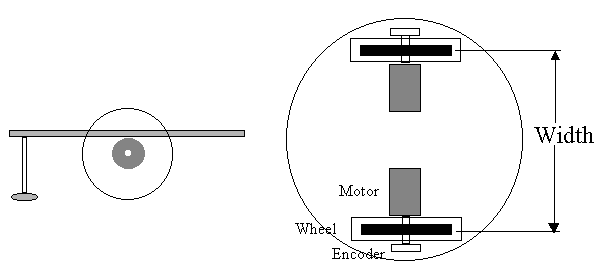
The first robot is the basic platform with two side mounted independently driven wheels which are used for both propulsion and steering. This robot generally has some form of caster mounted at one or both ends to keep it from falling over.

The robot in the drawing above has a round platform. The motor, wheel and encoder are all on the same shaft for simplicity. The equations don't care how you implement your drive setup. The motor is mounted below the platform with the wheels rotating through cutouts in the platform. There is a caster on the front end.
The basic characteristics which we might need in doing calculations are:
Width between
tires:
10 inches
Circumference of
tire:
10 inches
Encoder pulses per revolution: 100
Motor maximum
speed:
200 rpm
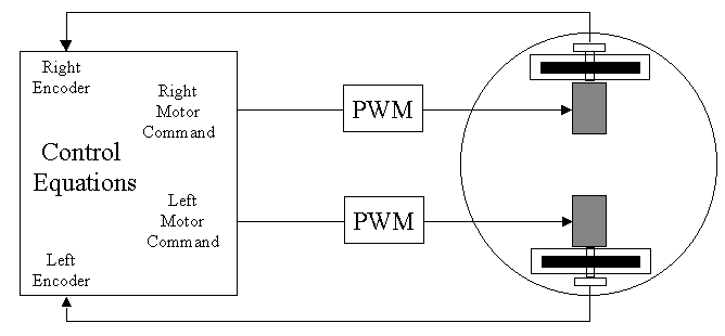
The control equations developed on later pages will output separate commands to each motor. This command will be assumed to drive a Pulse Width Modulated (PWM) signal to each motor such that the numeric output of the equation (which will be assumed to vary from -100 to 100), will determine a 0 to 100% duty cycle of power to the motor with positive numbers representing forward motion and negative being reverse.

This paper will talk about the computations in the Control Equations block. Converting the Motor Commands to PWM (or analog or anything else, if you prefer) and receiving the encoder signals and counting or timing them is up to you since it is so dependent on your particular robot and processor.
Commands to proceed forward (or reverse) will, of course, consist of commands to the motors to make them move the same distance as measured by the two encoders.
Commands to make the robots turn to the left or right will consist of a steering command signal which is added to one wheel and subtracted from the other so that one side of the robot moves farther than the other and the robot turns. By making the two motors move equally and opposite, the robot can be made to rotate in place which can be very useful.
Robot 2: Car type steering
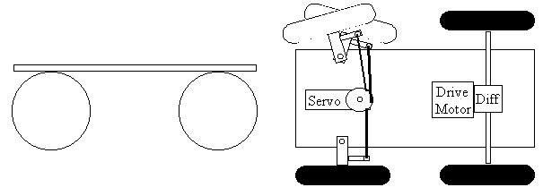
This robot is what you would get if you add a computer to a Radio Control racecar. The essentials are that I'm assuming the car is driven forward by a single motor which is driving the two rear wheels through a differential (or a single rear wheel); and the car is steered by an RC servo which rotates the front tires from left to right just like on a real car.

Note: the differential applies motor torque to both wheels while allowing one wheel to travel a different distance from the other. This is necessary (or at least desirable) in turns to avoid wheel slippage when going around corners.
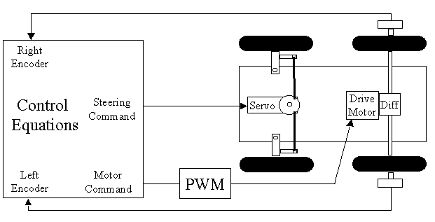
The drawing below shows the two controls to the car. The Drive Motor takes a single PWM signal just as each of the motors did in the Differential Drive car. This signal will, again, vary from -100 to +100.
The steering is done by an RC servo which goes to the POSITION commanded by the control equations. We'll assume that the command varies from -100 (full left turn) to +100 (full right turn). You get to convert that +/- 100 range into whatever pulses your servo requires to give full throw on the steering.

Note that I've chosen to put encoders on each back wheel. If your drive motor has an encoder built into it (before the power goes to the differential), that single encoder will give you the distance the robot has traveled. If you have to put encoders on the two drive wheels, you will have to average them in software to get the distance traveled. The two encoders also give you another method to determine how far the robot has turned. I have found steering with a servo in this way to be relatively inaccurate if you try to estimate the angle that the robot has turned from the commanded steering angle and the distance traveled forward. Using two encoders makes it as accurate as the differential drive robot above...which is quite accurate.
Note: Calculating how far the robot has turned as a function of the angle of the front wheels and the distance traveled seems like it should be simple mathematics. I thought so. At slow speeds, it probably can be pretty accurate; but, I was trying to go fast. I believe the errors I found came about because I was driving an RC servo to steer; and the servo takes some time to reach its new commanded value. I was doing my calculations based on the commanded servo position, and the robot was steering based on the actual position. The two were different enough to give unacceptable errors for my application.
Obviously, on this robot, a command is sent to the drive motor to make it move the desired distance as determined by the encoder(s). Steering is done by pivoting the front tires to the left or right AND THEN moving the robot forward or backward to get the robot's body to actually turn. That is the main difference between the two robots. The differential drive robot can turn without moving anywhere. The car type robot MUST move forward or backward to turn.
The basic characteristics which we might need in doing calculations are:
Width between
tires:
10 inches
Circumference of
tire:
10 inches
Encoder pulses per revolution: 100
Motor maximum
speed:
200 rpm
Steering characteristics will be defined later when they are
used.
By the way, I don't really want to get into doing all the calculations associated with Ackerman steering (as described above), so I'll sometimes simplify this robot to have a single wheel mounted to a servo in the front center. For the control equations it's pretty much the same thing.
Return to the Control law menu to select the next subject