
Line Sensor
The sensor described below has been found to be very good at discriminating a white versus a black surface. It is good for finding white lines on black floors or black lines on white floors. I've used it both for finding the white lines and circles in the Trinity contest, and for line following applications.
The spec sheet for the sensor can be found at: http://webserver.qtopto.com/ir/qrb111x.pdf and the sensors can be bought at Digikey (www.digikey.com) as their partnumber QRB1114 for$1.30 each.
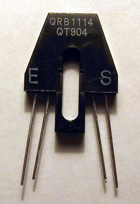
The spec sheet shows all the pin identifications but (considering the part is symmetric) doesn't say which end is which. The actual part is labeled with an "E" on one pair of leads and an "S" on the other. The "E" stands for emitter and is the photodiode end; the "S" stands for sensor and is the phototransistor end. No application notes seemed to be available.
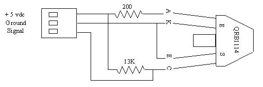
The above circuits show how to drive and read the sensor. The circuit on the left uses a +5 vdc power source through a 200 ohm resistor to drive the emitting LED. The circuit on the right provides a voltage output proportional to the amount of light received by the sensing phototransistor. Using the above resistor values gave petty good results. A tape of black electrical tape on a white sheet of paper would cause close to full range voltage change on the output at ranges between 1/8 (or even 1/16) inch out to about 3/8 of an inch. I've been using the sensor at a distance of 0.25 inches reliably.
Decreasing the resistance on the diode (to 100 ohms) to increase the intensity of the IR beam resulted in a slightly larger max range (maybe 1/2 inch) but at this resistance, the black tape caused enough reflectance to make the sensor think it saw the paper at short ranges (less than 1/4 inch).
Since the detector and emitter are mounted at an angle to each other, best detection is at a distance from the sensor base of 0.15 inches per the spec. The angular geometry also means that if even the white surface is brought too close to the sensor surface that the reflectance will be lost and the sensor will think it is seeing the black tape. This distance seems to be about 1/16 inch.
The resistance on the transistor is somewhat arbitrary. It is high enough to give a good voltage swing and low enough that ambient light does not tend to trip the sensor too much. I suspect that any resistor from 10 to 20 K will probably work ok.
The voltage swing of the output was generally in the range of less than 1 volt to greater than 4 volts; but as the distance from the paper/tape to sensor increased to 3/8 of an inch or more, the voltage swing reduces. Some circuitry may be necessary to provide a good logic signal for the processor. I used a 339 comparitor set to 2.5 volts(since it was handy and adjustable). Running the signal into a 74hc14 Schmitt trigger, as is done on the lynxmotion line follower kit, should work just as well. In practice, I found that the input circuit to my 68HC912B32 has a Schmitt trigger effect and I could wire the output (as marked above in the circuit drawing) directly to my processor.
The sensor has an "IR transparent plastic cover for dust protection " (quote from spec sheet). The cover looks dark and I suspect it also filters out much non-IR light. Performance in ambient light seems to be pretty good. Normal incandescant overhead lighting has little impact. A high intensity lamp lighting the area of the test from 12 inches away (but not directly on the sensed area) tended to turn on the photo transistor a bit, but not enough to swing the output voltage half way.
The sensor is pretty immune to sunlight. I tested the sensor outside with a bright sun shining.. The sensor works if you provide just a bare minimum of shading. just keep the sun from hitting the exact area where the IR reflection takes place and the sensor still works. I had it working pointed downwards toward the paper and tape on the floor with direct sun hitting the paper just 1/4 inch away from the sensor area.
Should be no problem working in a room with some sunlight coming in as long as it's not hitting directly on the line-following track. Even then, if you put a little sunshade above the sensor, it could shade the area where the sensor is looking.
The following drawing and picture shows how I implemented the circuit. It wires the sensors to a 3 wire IDC connector. The resistors are located in the wiring under the shrink wrap.

 And
finally, two of the sensors installed on my robot
And
finally, two of the sensors installed on my robot