Wheels
Obviously, you can use any size and shape wheel you want...as long as you can fit it through the cutouts on the platform. Larger diameter wheels will allow the robot to move more quickly; but with less torque to overcome obstacles. Smaller wheels give more torque and less speed.
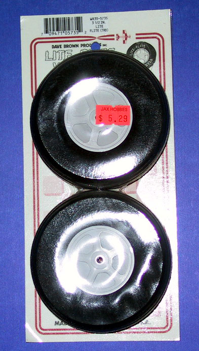
Parts required: Two 3 1/2 inch Lite Flite wheels
10 2-56 machine screws and nuts 1/4 inch long minimum to 3/8 inch.
Note: if you can't find suitable screws, you can get them at www.smallparts.com
Tools required: large (1/2 inch or more drill bit) optional, to gouge out protrusion on side of wheel.
3/32 and 3/16 inch drills and hand drill or drill press.
razor blade, also optional, but some sharp implement.
A 3 1/2 inch diameter wheel has been found to work well with this robot. A usable example is made by Dave Brown Products as part of their LITE FLITE series. These wheels are commonly available at hobby stores for use on model aircraft. There are two part numbers available in 3 1/2 inch size. The WH35-5535 has a flat surface on the tire. The WR35-5735 is the same size but with a treaded design. The description below uses the treaded version
If you can't find suitable wheels locally, you can order these wheels from www.hobbypeople.net as their part numbers 218535 for the flat version, and 218558 for the treaded.
.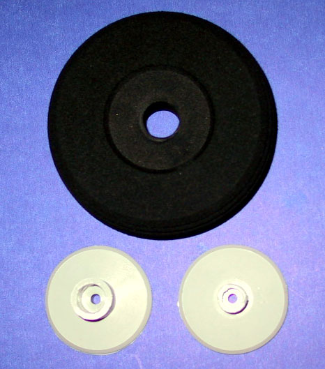
To attach the hub to the wheel, it is easiest to disassemble the wheel into the two side flanges and the tire, as can be seen above. This can be done by just prying the two flanges apart. A large screwdriver inserted down one side works. Or maybe even pull them apart by hand while twisting. They are attached by friction and can be put back together just by pressing them together by hand.
The wheel must be attached to an output wheel which can be attached to the servo. In the parts kit included with each CS-60 servo is a wheel about 1 3/8 inch in diameter. It fits well with the hub of the wheel.
The following describes how the wheel can be attached to the output hub.
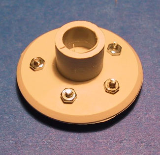
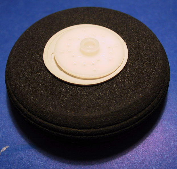 If you hold the output
wheel to the side of the wheel hub (as above), you will see that it fits well in size, but does not lay flat against the
wheel since the wheel has a small, about 7/16 inch diameter, protrusion around
the axle hole. This protrusion keeps the rim of the output hub from lying
flat against the rest of the wheel. If you remove this protrusion,
the wheel will lay flat against the wheel providing for a better connection and
less probability of wobbling.
If you hold the output
wheel to the side of the wheel hub (as above), you will see that it fits well in size, but does not lay flat against the
wheel since the wheel has a small, about 7/16 inch diameter, protrusion around
the axle hole. This protrusion keeps the rim of the output hub from lying
flat against the rest of the wheel. If you remove this protrusion,
the wheel will lay flat against the wheel providing for a better connection and
less probability of wobbling.
 Believe
it or not, the top picture has the wheel lying tilted across the hub
protrusions, and the lower picture is lying very flat. Doesn't look much
different in the pictures though.
Believe
it or not, the top picture has the wheel lying tilted across the hub
protrusions, and the lower picture is lying very flat. Doesn't look much
different in the pictures though.
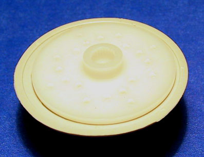
The protrusion can be removed by any means you wish. I used a large drill bit applied to the axle hole to remove most of the protruding material. I then used a razor blade to clean up the surface to make it flat.
Now the output hub lies flat against the the wheel, and we only have to attach it.
Thinking ahead, when assembled, we will attach the wheel and output hub combination to the servo by inserting that small screw that came holding the original output wheel to the servo. In order to do so, you have to enlarge the axle hole of the wheel to a larger size so the screw will fit through. The screw head has a diameter of 0.181 inches; hence if the hole is drilled out to 3/16 inch (0.1875 inches) the screw should fit through OK. So do so, drilling all the way through the wheel from one side to the other; or if you have the two hub halves apart at this time, you can drill them separately.
The output hub may be attached to the wheel by an appropriate adhesive, or by screwing it into place. Since I don't know an appropriate adhesive for sure, and I have seen the wheel which Mike Belanger assembled with screws and passed around at the last meeting, I'll use that technique.
The output wheel has many holes predrilled in it. Unfortunately, they do not match up with the 5 ribs in the wheel which are the best places to put screws. So, one way to do it is to line up one of the holes in the hub (one of the four outermost) with the center of one of the five ribs. It doesn't matter which side of the wheel you use. With a pen, make a mark on the rib through the hole. Then drill through the wheel at the mark. I chose to use 2-56 screws, so I used a drill just large enough for the screw. A 3/32 inch drill will work fine for 2-56 screws. Then I drilled out the hole on the hub and temporarily assembled them with a screw to verify that the parts aligned properly (mostly that the output wheel is centered on the hub when the screw is in). Place a mark on the wheel and hub near the screw, so you can put them together again at the same angle. I then took it apart again. Noting where the hole had been drilled in one rib of the wheel, I marked and drilled through the wheel at about the same spot on the other 4 ribs. Location of these four holes isn't critical as you will be drilling the output hub holes to match. Then, attach the output hub again with one screw through the original hole. Holding the hub carefully aligned with the wheel, drill back through the holes in the wheel so that a hole is drilled in the hub. After the first hole, put a screw through this new hole and verify that with two screws inserted, the parts are still aligned. If so, go ahead and drill out the other 3 holes on the hub. If it is not aligned, remove the screw and try another hole holding it more accurately. Once you get it right you can go back and redrill the faulty hole.
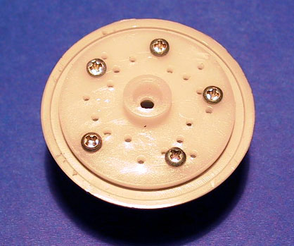
Now, you can insert all five screws and tighten them into nuts on the inside of the wheel. Reassemble the tire and the two wheel halves and you have a completed unit. The foam of the tire will give to make room for the nuts on the inside.
 Attach
the completed wheel assembly to the hacked servo motor, and you've got (half of)
your drive system for your robot.
Attach
the completed wheel assembly to the hacked servo motor, and you've got (half of)
your drive system for your robot.