Now, if the proportional and derivative gain worked so great, as described above, why do you need an integral term in the equation?
Mainly because of offsets and biases in the system. For example, if you are steering with a hobby servo and a car type steering system, and the digital zero point you have in software (the approximately 1.5 millisecond point) does not result in the robot running straight ahead, the equation is going to have to provide a continuous signal to the servo (an offset from 1.5 msec) to keep the robot going straight. In the previous examples, with a gain of 2 degrees of steering per inch of distance error, an offset of 5 degrees on the servo steering would require 2.5 inches of distance offset to cancel it out and go straight . Maybe for your purpose 2.5 inches of error is OK. But sometimes you will want better accuracyÖthat is the system should compensate for any such errors. Thatís what the integral term can do.

Letís say we already have a proportional/derivative system which has turned to robot toward the line; but, for whatever reason , the error doesnít go to zero; that is the robot cruises along parallel to the reference line, but offset to the left or right. The integrator will create a signal to cancel out that bias and return the error signal to zero.
An integrator is a device (or equation) which calculates the integral of the input over time. The way an integrator works is to use the input to create an output which will continue to grow until the input is reduced to zero. This is implemented on a computer by adding the input to the previous output of the integrator each time the integrator equation is performed. This would be something like:
IntegratorOutput = Integrator Output + IntegratorInput
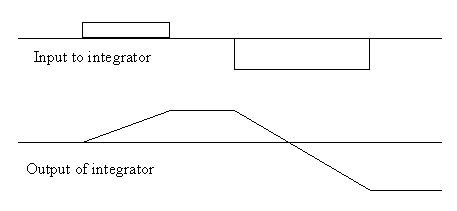
To clarify, the next figure shows how an integrator responds to step inputs over time.

The integrator is effectively calculating the offset distance (error) times the Time that that error exists for . If the input stays at 5 inches for 2 seconds, the integrator output will ramp up from zero to 10 inch-seconds. If the error then goes to zero, the integrator will remain at 10, if the error goes negative, the integrator will start to reduce its output.
An integrator is easy to implement in software. All you do is take the current value of error and multiply it by the period of each calculation cycle (e.g. if doing control laws at 20 times per second, the period would be 0.05 seconds). You then keep a running summation of these calculations.
Loop
Integrator = Integrator + (error * 0.05)
EndLoop
The only thing you have to do is initialize the integrator to a desired value (usually zero) before you start running the loop.

steering = Kintegral * integrator output
Note that this new integrator circuit is using the reference error as its input. Thatís because the reference is the signal youíre really trying to track (not the rate signal, which is the only other signal in this example. So if the error signal is not averaging zero, that is, itís staying off to one side, the integrator will slowly increase in value. That integrator output is summed into the steering command with a sign that will cause the steering to move in the direction to reduce the error. Eventually, when the integrator output gets large enough to cancel out whatever bias was causing the error, the error will go to zero and the integrator output will remain constant and the robot will proceed with zero error.
Return to the Control law menu to select the next subject