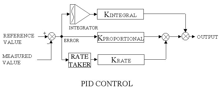

A block diagram is similar in concept to a wiring diagram or a software flow chart. It gives a pictorial representation of the control computations.
Block diagrams provide a clear concise picture of what a control system consists of; once you know what the symbols mean. Most of the symbols represent simple mathematical terms.
As a general rule, signal/computation flow in a block diagram is usually from left to right with the input references on the far left, computations in the middle, and outputs on the right. Feedback signals representing the results of the outputs will return from the right side, or may just be shown as entering the left side.
Blocks specify what operations will be done to the signals and lines are used to show that signals are transferred from one operation block to another. There are a few other symbols used on a block diagram which will be described below..
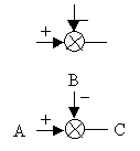 The
summation symbol just means that two or more signals are added together. The
signals coming into the summation are usually on the left, top and bottom and
the resulting sum comes out of the right side. Often, the inputs are
marked with a "+" or "-" sign to indicate whether they are
added or subtracted to create the sum. If a sign is not indicated, it
usually means plus. If the arrowheads are left off the inputs,
it is usually possible to determine which are inputs by looking at the other ends
of the lines.
So, for the example to the left, this summation indicates that C = A
- B.
A block may define any type of mathematic operation. 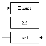 A simple
gain is usually indicated by a block with an input signal on one side (usually
left) and an output on the other side. The gain itself is often specified
by a name beginning with a K and followed by a short descriptive name; e.g.
Kproportional, Kintegral etc. This gain may be a fixed value or a computed
value. Sometimes the gain may be specified more specifically within the
block. For instance, if it is a constant, the number may just be in the
block. The input signal to the block may have an arrowhead to
indicate it is an input. When the signal flow is left to right, the arrow
will often be omitted. The gain function may be more complex such as square root
(sqrt) or may be defined in may other ways. But, whatever it
is, the function is applied to the input to generate the output. A complex
function will sometimes not be specified within the block but will be more fully
defined elsewhere on the sheet, or in the code. The block will just
have a general
description of the operation in the block, or a reference to where the function
can be found.
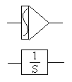 An
integrator is defined elsewhere, but it may be shown on a block diagram using
the top symbol on the left. The squiggle line on the left side is the standard
math symbol for an integral. I will use this symbol.
In other block diagrams, you may see it indicated as in the lower block as
"1/S". This is the Laplace Transform description of an
integrator .
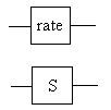 A
ratetaker or differentiator determines the rate of change of the input signal
and supplies that as the output. There are a number of ways of computing a
rate signal. Generally, I'll define how to calculate rate in text and just
put a block called rate (or rate taker)in any block diagrams.
The Laplace transform version of a differentiator (rate taker) is shown in the lower
drawing as an "S".
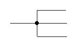 Lines
between blocks work very much like electrical wires. One of the
lines, usually the one coming from the left, will come from an external input
signal or an output of another block and that line may go to one or more
additional blocks where it will be an input. The dot may be used to
clarify that all the wires are attached together and the signal travels down all
paths.
 A
switch may be used to indicate that a signal may be transferred or not depending
on the state of some logic. The logic will usually be written under
the switch, or a line may go from the switch element to another block where the
logic is performed.